3D Scanning or Tactile Measurement — Which One Fits Your Part
3D scanning and tactile measurement answer different questions. A tactile CMM measures a few points with micron-level accuracy and is the reference for tight tolerances, datums and GD&T. An optical 3D scanner captures millions of points in minutes and shows the full shape of the part in a deviation map. The right choice depends on the tolerance, the geometry and the surface of each part.
The difference is how many points and how accurately
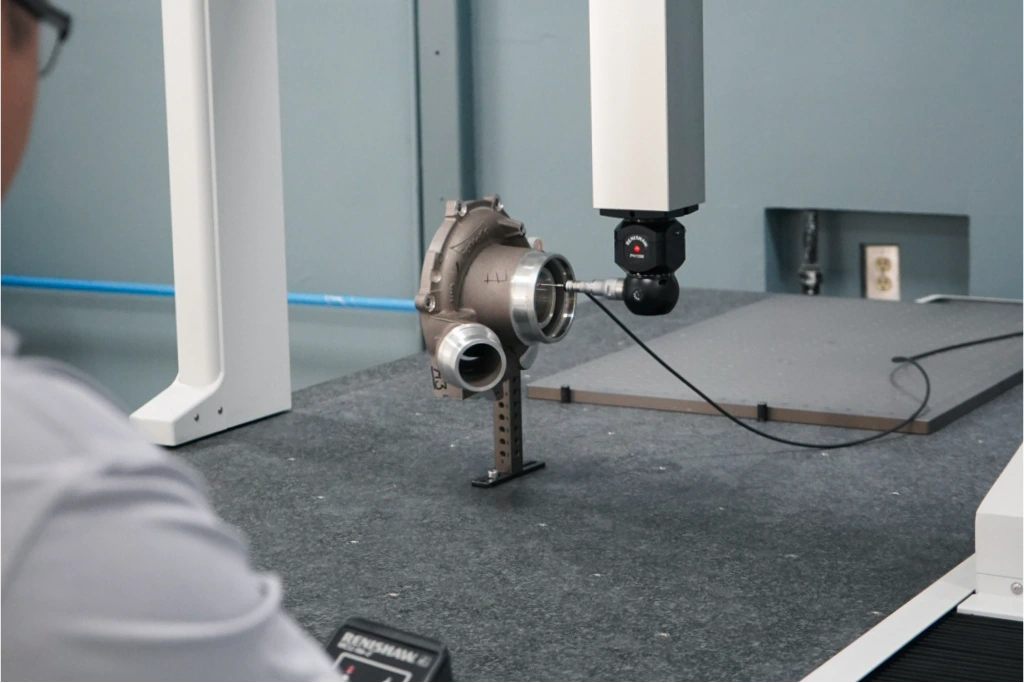
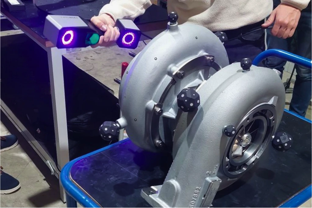
A tactile coordinate measuring machine touches the part with a probe and records each point with an accuracy in the order of 2 µm. The Coord3 Universal, for example, declares an MPEE0 from 1.9 + 3.0·L/1000 µm under ISO 10360-2, with a PH10 head and a TP20 probe. Optical 3D scanning projects structured light or laser onto the surface and rebuilds a dense point cloud in a single pass. The ZEISS T-SCAN hawk 2 declares a volumetric accuracy of 0.02 mm + 0.015 mm/m, with an acceptance test based on ISO 10360. The two figures are not comparable because they come from different tests, and that is exactly what separates the two technologies — tactile measurement measures one feature with the lowest possible uncertainty, optical scanning measures the whole part.
3D scanning vs tactile measurement compared
| Criterion | Tactile measurement with a CMM | Optical 3D scanning |
|---|---|---|
| Output | Discrete points on the programmed features | Cloud of millions of points and a color deviation map |
| Typical accuracy | Microns, declared under ISO 10360-2 | Hundredths of a millimeter, depending on the system and the volume |
| Acceptance standard | ISO 10360-2 and ISO 10360-5 | ISO 10360-13 and VDI/VDE 2634 Part 2 and Part 3 |
| Strong at | Diameters, positions, datums, perpendicularity, threads and deep bores | Freeform surfaces, sheet metal, injection-molded plastic, castings, flexible parts |
| Surface | Unaffected by color and gloss | Gloss, black or transparency may require a matting spray |
| Time per part | Depends on the number of features; the program is reused in series | Minutes for the full surface |
| Typical use | Dimensional release and control of tight tolerances | First article, reverse engineering, warpage analysis, comparison to CAD |
The standards each technology is declared under
Tactile measurement is accepted and reverified with ISO 10360-2, which measures the length measurement error and repeatability, and ISO 10360-5, which evaluates the probing error with one or several styli. In Mexico, ISO 10360-2 has a national adoption, NMX-CH-10360-2-IMNC. Optical 3D scanning is evaluated with VDI/VDE 2634 Part 2, for single-view systems based on triangulation, and Part 3, for systems that combine several views. The test uses spheres, ball bars and planes with a diffuse surface, and declares the probing error on the sphere, the sphere spacing error and the flatness error. Since 2021 there is also ISO 10360-13, the part of the series dedicated to optical 3D systems. Asking for the standard together with the figure is the only way to compare two systems of the same technology.
When tactile measurement is the right fit
Tactile measurement is the right fit when the tolerance is in microns or a few hundredths and the drawing carries GD&T under ASME Y14.5. The CMM builds datums from real surfaces, measures true position, perpendicularity and cylindricity with the lowest uncertainty in the shop, and reaches into deep bores or slots where light cannot go. It is the natural choice in precision machining, in engine and transmission components for automotive parts, in aerospace and in medical devices with functional tolerances. In series production, the CMM program is written once and measures every part the same way, which makes the gage R&R study and statistical process control easier.
When 3D scanning is the right fit
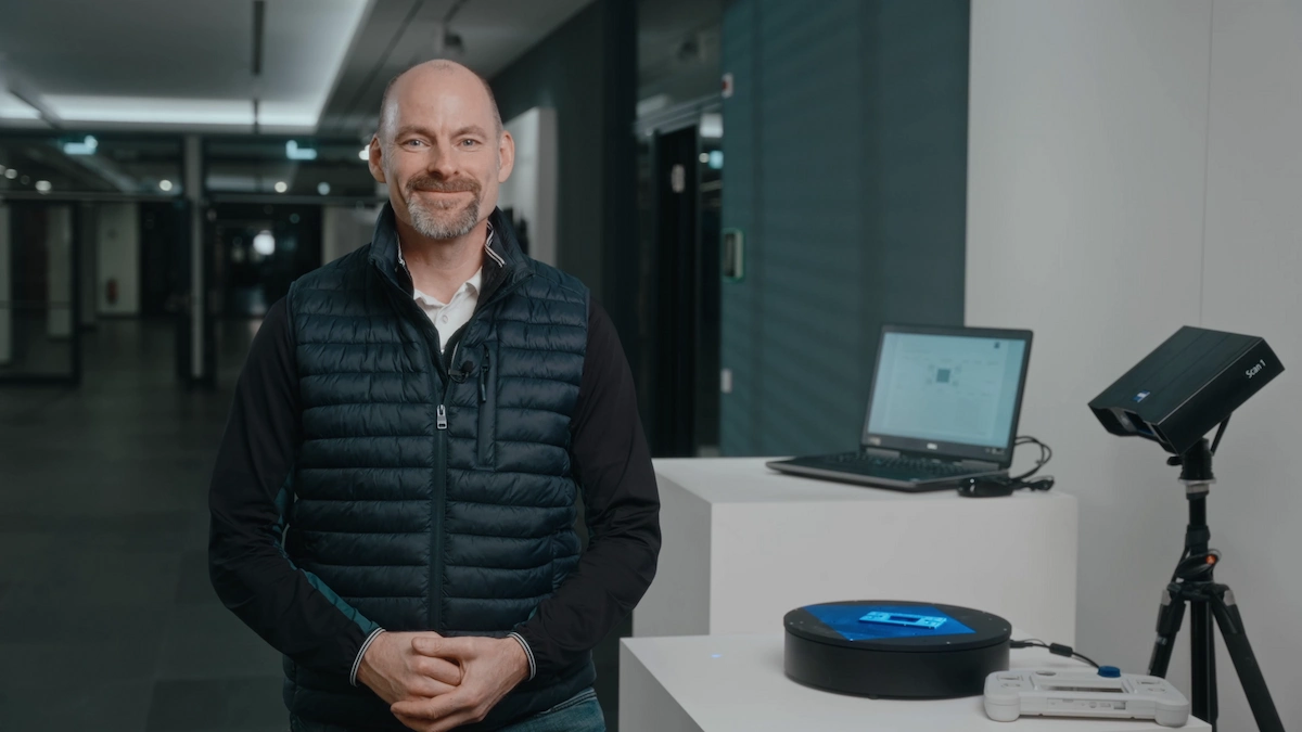
3D scanning is the right fit when what matters is the full shape, not a handful of dimensions. A stamped sheet metal part, an injection-molded plastic housing or a casting is compared against its CAD model in a color map that shows at a glance where it is out of tolerance and by how much. The scanner also digitizes tooling and parts without a drawing for reverse engineering, and measures flexible or thin parts that a probe would deform, without contact. In first article inspection and in mold and die tryout, seeing the whole surface saves iterations. ZEISS offers this technology in stationary systems such as the ATOS Q and the GOM Scan 1, and in portable systems such as the T-SCAN hawk 2.
Surface and material also decide
Optical 3D scanning depends on light returning to the sensor. Very glossy, black or transparent surfaces, such as mirror-machined aluminum, black plastic or glass, return little signal or false reflections, and are handled with a matting spray or with a narrow-band blue light sensor. ISO 10360-13 assumes cooperative surfaces for that reason. Tactile measurement is unaffected by color and gloss, but it needs the part to withstand the probing force and the feature to be reachable by the stylus. A rubber part, a film or a very thin sheet calls for scanning; a deep, narrow bore calls for a probe.
Can 3D scanning be used to release a PPAP?
3D scanning can be used to release a PPAP when the customer accepts it and the system demonstrates capability for the tolerance it measures. The AIAG PPAP manual requires dimensional results for every characteristic on the drawing, and the MSA manual requires a capable measurement system, with an acceptable gage R&R study, without prescribing a technology. In practice, many OEMs accept the color map for surfaces and profiles, and require the tactile CMM for critical characteristics with tight tolerances. Confirming with the customer’s quality engineer what is accepted for each characteristic avoids resubmitting.
The two technologies can also be combined
Tactile measurement and 3D scanning are not mutually exclusive, and many plants use both on the same part. A CMM with a continuous scanning head, such as the Coord3 Universal with SP25M or REVO, captures dense profiles without losing tactile accuracy. A multisensor system such as the Micro-Vu Excel combines optical, tactile and laser measurement in a single machine. And in first article inspection it is common to scan the full surface to locate the critical areas and then measure them on the CMM. The rule is to assign each feature the technology with the right uncertainty for its tolerance.
How to decide with your own part
The fastest way to decide is to measure the real part with both technologies and compare the results. 3D Metrisoft distributes Coord3 CMMs, ZEISS scanners and Micro-Vu systems, and offers a free demonstration with the prospect’s own parts, online, at their plant or at the Tech Center in Queretaro. The 3D Metrisoft laboratory in Queretaro also performs dimensional measurement per part for those not yet ready to invest in equipment, with PJLA accreditation 89786 for dimensional inspection.
Frequently Asked Questions
The tactile CMM is more accurate per point. A bridge CMM declares errors in the order of 2 µm plus a length-dependent component under ISO 10360-2, while an industrial 3D scanner works in the order of hundredths of a millimeter. In exchange, the scanner measures the full surface in minutes.